New Development: GL.control

Everything under control: New software enables reduced compilation time, shorter machine downtime, and intuitive operation
To keep up with the rapid developments in laser micromachining, not only do the tools and machines need to be regularly adapted to new requirements, but the software used in these processes also needs to be continuously expanded and improved. In 2016, the laser system specialist GFH GmbH began optimizing and partially redesigning the GL.control software used for planning, adjusting, and compiling machine data. Version 7 is intended to optimize the runtime of the laser machines in the future while simultaneously reducing downtime. Furthermore, the user interface and operating interface have been extensively revised and expanded: Two significant innovations include the fully integrated solution for replica creation based on point clouds captured by measurement technology and the ability to compare the target CAD model with captured measurement data. The first machines with GL.control 7 are expected to be delivered by the end of 2017.
"We began fundamental optimization of our operating software, GL.control, last year to unify both machine control and compilation of machine data into a single solution," reported Florian Lendner, a member of the management board at GFH GmbH. "In the old version, the CNC machine control was performed separately using a conventional hardware keyboard, but now it has been included," said Florian Lendner. They also aimed to replace the conventional screen with one featuring integrated touch functionality to enhance usability and align with the current standard, the Flat Design. The 27" QHD touchscreen was specifically designed for the new GL.control software, boasting a resolution of 2560 x 1440 and is operable either with a stylus or by hand.
Compiling machine data was also challenging in the old version, as only one folder with compiled data was maintained. Re-uploading an unchanged project often resulted in the need to recalculate all vectors. This process not only consumed additional time but also required employee capacity. Now, this step is only carried out when necessary and with great precision, thereby enormously reducing longer machine downtime. Diagnostics capabilities have also been enhanced for any errors occurring during the machining process. The quality of the machined workpieces and the functional features of the previous version had to be preserved in the process. The development team emphasized ensuring that both old and new hardware are supported by the optimized GL.control software. "Another challenge was to bring the OpenCascade framework for 3D visualization and editing, as well as QT for graphical representation, up to date with the latest technology," stated Lendner. "However, this caused some existing modules to become incompatible with the new software version. Nevertheless, we managed to find solutions to these issues and establish new, practical functionalities," remarked Lendner.

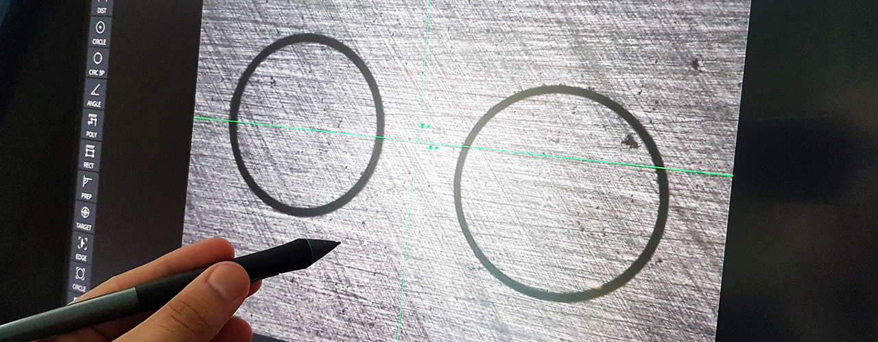
GL.control 7 with touchscreen
The 27-inch QHD touchscreen was specially designed for the new GL.control 7 software, featuring a resolution of 2560 x 1440 and supporting input either with a stylus or by hand.
New CNC features for enhanced performance
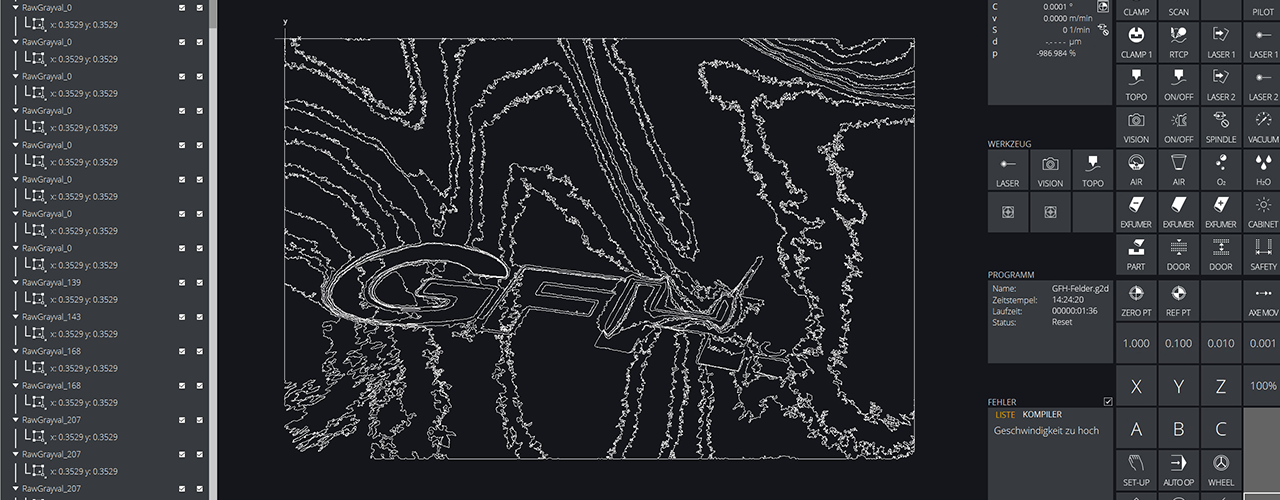
These new features of GL.control have been divided into several individual areas and integrated into the user interface: GL.status, for instance, displays all relevant data in a manageable window, with the order of status windows freely configurable. Status information can also be displayed in a separate window where the CNC operator terminal is implemented. GL.jobs enables the consecutive execution of multiple programs from different GL modules. Additionally, it's now possible to automatically open the cabin door or turn off the laser diode at the end of the job list. The new GL.nc features allow for more convenient editing of NC programs: Enhanced syntax highlighting makes the code easier to read, with command groups and keywords displayed in different colors. Function blocks must always be enclosed in brackets, and clicking on one bracket automatically highlights the corresponding second bracket, aiding in recognizing function blocks. "Thanks to the new macro functionality, the NC code can also be used in other programs," says Lendner. "Previously, the code had to be painstakingly copied, leading to errors. Now, a change in the code only needs to be made once in the macro." The new GL.control also includes an improved graphics engine based on OpenGL 2.0. This allows for very fast display of 2D and 3D preview images of the machining process on the screen. Micro-bridges can be inserted to prevent cut-out components from falling out during the process. Additionally, automatic corner rounding is now possible. When processing grayscale images, the previous solution realized grayscale either through varying laser power or a varying number of passes. With the new GL.greyscale function, outlines of different grayscale levels can be extracted from an image and processed with different hatchings. For example, a black area in the image can be assigned a hatching distance of 1 µm and a light gray area a hatching distance of 100 µm—this allows for better implementation of different grayscale levels on the component. The GL.trepan function has been further developed to create variable parameters for individual lines of a trepan sequence. Adjusting the z-axis during a running sequence is no longer a problem. Additionally, optimized search and filter options and a quick preview are available.

GL.designer2D
The new GL.control7 also includes an improved graphics engine based on OpenGL 2.0. This allows for very fast display of 2D and 3D preview images of the machining process on the screen.
Full component detection using camera and specialized sensor
The enhanced GL.vision function is used to precisely determine the respective coordinates on a component using a camera. It's often necessary to perform calculations with these coordinates. For example, to align a component, one can determine the position of two calibration marks on the component and calculate the rotation angle of the component using trigonometric functions. "Previously, the coordinates recognized by the camera had to be exported to NC variables first. Then, mathematical operations could be applied to these coordinates in the NC program," said Lendner. Now, it's possible to perform mathematical operations directly in the GL.vision program with the recognized coordinates. Additionally, the GL.topo function has been revised: Using a highly accurate distance sensor, the topography of the component to be machined is scanned. This provides a digital point cloud within the software, which can then be machined using the GL.designer-3D function. Thus, an exact replica of the scanned component is obtained. If there is still residual material on the component after a 3D machining—for example, because the desired depth has not been reached—the topography scanning allows comparison of the captured point cloud with the original component, enabling easy and quick post-machining of the remaining material.

GL.greyscale
With the new GL.greyscale function, a hatching distance of 1 µm can be assigned to a black area in the image, and a hatching distance of 100 µm can be assigned to a light gray area—this allows for better implementation of different grayscale levels on the component.
Stay fully informed even offline
Additionally, GFH has developed GL.offline, a specialized version of the optimized GL.control that can run on any Windows PC. This allows programs to be prepared on this PC to avoid any machine downtime. In the new version, it's possible to directly connect to a machine via the network and upload created programs. Complex program compilation can also be done on the offline PC, ensuring no machine downtime here as well. Currently, the final tests of GL.control 7 are being conducted on GFH's own precision manufacturing machines in Deggendorf. "Starting from the end of the year, all new machines will be shipped with it," explains Lendner.